Education
Variable Gradient Model: An Approach To Create More Efficient Decompressions
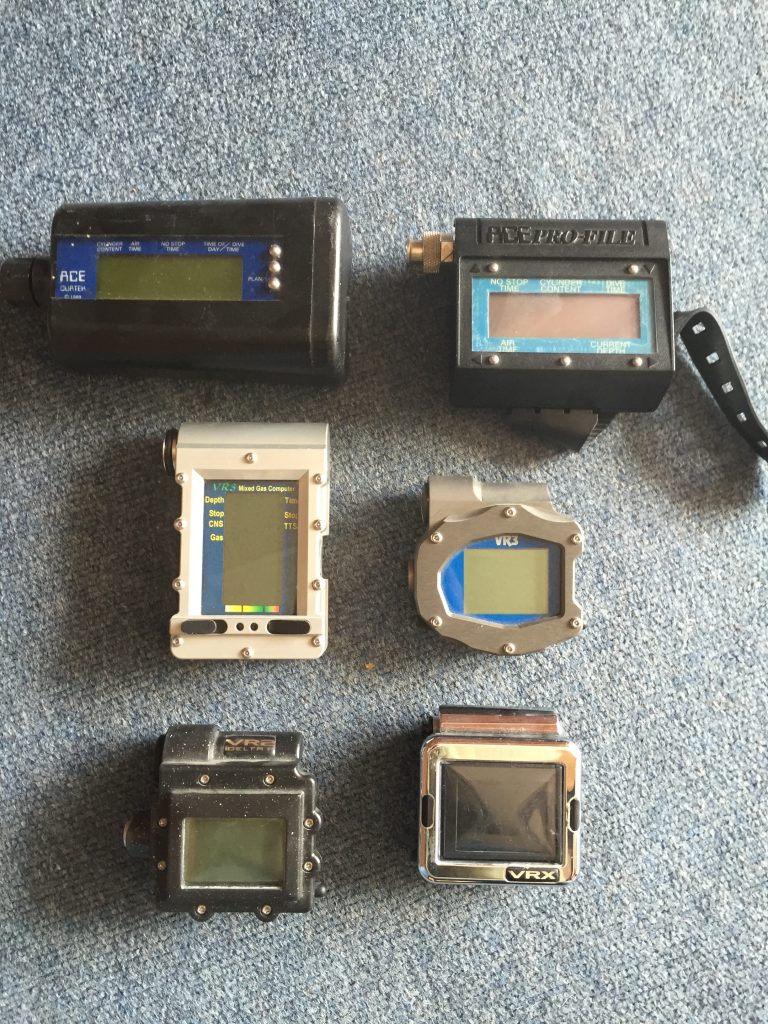
British tech pioneer and inventor Kevin Gurr has been building dive computers since the early 1990s, including the world’s first mixed gas diving computer, the VR3, which he launched in 1997, through his former company VR Technology Ltd. based in Dorset, UK. He also designed and built three sport rebreathers. Now the Maritime Technology Officer at Avon Protection managing military rebreathers, Gurr discusses an innovative modification of gradient factors that he developed for use with his various devices.
by Kevin Gurr
Header Image: by K. Davidson for Halcyon.
This article is not designed to go into the finite detail of decompression modeling; other people have achieved this far more successfully. It is intended as a snapshot view of what is currently available in Avon Protections’ MCM100 military rebreather, which I helped design, hopefully with a level of technical clarity so that the reader can evaluate for themselves the merits of the differing methods.
The human body cannot currently be mathematically modelled. Not only are individuals different because of age, fitness, pulmonary and cardiac (PFO) defects, but they also vary on a daily basis due to hydration, stress, exercise, micro-nuclei generation, and many other factors.
So how does the diving community conduct thousands of safe dives per year? Some experimentation has historically been done to produce ‘reasonably safe’ decompression tables that ‘fit’ most people for a shallow water (primarily air diving) environment. In modern technical diving, much of the deeper diving we do is simply an extrapolation of the early shallow water research. We now know that this does not always work.
Shallow water diving is relatively well documented and we have historical figures to work with, which is only just starting to occur with deeper diving. Let’s review the basic decompression theory so that we may investigate possible ways to deal with the problem.
Consider the Buhlmann system of decompression: it is assumed that each of the hypothetical tissue compartments can safely experience an over-pressurization during a reduction in pressure (ascent) after a pressurized exposure (time at depth) which has allowed them to absorb gas.
The subsequent decompression profile that is generated on the ascent should not exceed the tolerated over-pressure value, or M value — a theoretical construct for the theoretical controlling tissue compartment within the body, in order to avoid decompression illness (DCI). As each compartment comes into play and the relevant M value is reached, a decompression stop profile is generated.
Figure 1 represents a very simplistic example involving just one of the fast tissues which will control the primary ascent phase. The M value for this compartment is shown as a straight line. If the diver controls the ascent, the inert gas loading in the compartment will stay on or below the M value line. If they do this, let’s assume they are using 100% of the available M value, which means there’s no extra safety margin for that dive; they are theoretically diving right on the edge of the model.
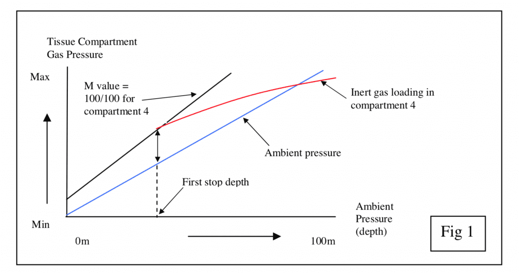
For a typical bounce dive, Buhlmann standard practice has been to allow a rapid ascent to the first stop to generate a high level of off-gassing. Doing this, the gas loading in the fastest compartment will be on or near saturation at the bottom depth (the slow tissues are only partially saturated). This means that the fastest compartments will control the initial ascent since their gas loadings will be near or on the tolerated over-pressure value (M value). The first stop depth is set when the controlling (fast) compartment is nearest to the M value. The example only shows up to a point where the first stop starts and does not detail the other compartments or the remaining decompression.
Using gradient factor terminology, the M value line is the 100/100 reference. The first 100 describes how close (in percentage) to the M value line the first stop is, and the second 100 describes how close the final stop is. Thus 100/100 has no added safety margin compared to the M value. In the complete picture, each compartments’ M value and each compartments’ internal pressure right through to the end of the dive (not just to the stop as drawn) would be displayed on the graph each with the same 100/100 gradient. The slower compartments would reach their M value during the final decompression phases while the faster compartments control the deeper decompression.
The gradient factor system modifies the M value by taking a percentage of the difference between the M value and the ambient pressure value. As a simple example to illustrate how Gradient factors work, using 80% of the M value as the controlling value (80/80 line) produces a line on the graph (figure 2) below the 100/100 line, having the effect of reducing the compartments allowed over-pressure value and generating a deeper decompression stop.
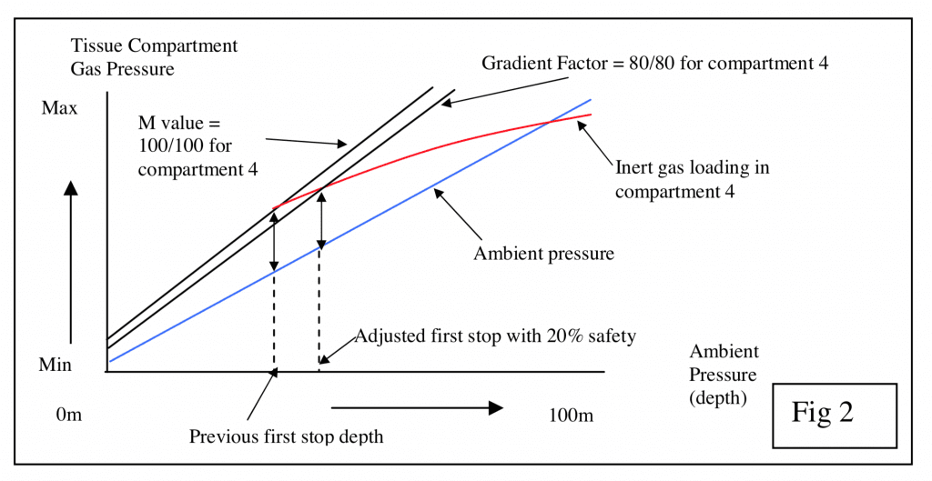
Again, in the complete picture all the adjusted M values and compartment pressures would be plotted, adding safety to the whole decompression profile.
As most of these early dissolved gas based tables were formulated around relatively shallow water air range dives, they do not suit deep water dives, although historically they have often been extrapolated for use in deep-water. While these tables have a varying solution for different depths they were depth limited.
So what about Pyle stops? Technical diving pioneer, ichthyologist Richard Pyle developed a practical solution that divers could understand for modifying the decompression profile to reduce the excessive over-pressurization of the controlling compartment at the deep stops. He found that by stopping and venting a fish’s swim bladder below the first tabular stop depth, he ‘felt better’ at the end of the decompression. He was in effect allowing the faster compartments’ pressure to reduce before ascending to the tabular first stop and not reach its M value peak.
The downside of this was that other compartments were still on-loading gas, which could generate an additional decompression obligation in shallow water. He was applying a safety factor that only had an effect on the deeper stops. This had the potential to allow the slower compartments to become closer to their M value during the shallow water decompression phase unless additional safety factors were applied.
Now we move onto bubble models (VPM etc.). Put very simply, bubble models attempt to explain the growth phases of inert gas bubbles and their subsequent effects. These models focus on the first part of the ascent where the bubbles grow, and by doing so, claim they can lead to a predicted reduction of the decompression obligation in shallow water. However, because of this decompression reduction, some dives generated decompression stress which could not be explained. In recent years, these bubble growth models have gone through several iterations as a result, and new evidence suggests that “deep stops” generated by bubble models may not be more efficient than shallower decompression.
A common (but complicated) solution to reduce the problem was to combine what was known about shallow water decompressions (Buhlmann) with the deep water bubble model. We know this is still an incomplete solution as phenomena such as arterial bubbles and other effects are not taken into account. Bubble models give an explanation and provide a working model of what Richard Pyle tried to implement practically from a technical divers standpoint.
A recent tool, which provides a simpler solution between Buhlmann and the bubble models, has been to use gradient factors with a dissolved gas model which in turn modifies the M values of the controlling compartments (Baker). This has the effect of combining a bubble with a dissolved gas model style decompression profile.
Gradient factors can further mimic bubble models by using two different gradient factors to control the decompression: one that primarily references the deep stops, and one the shallow.
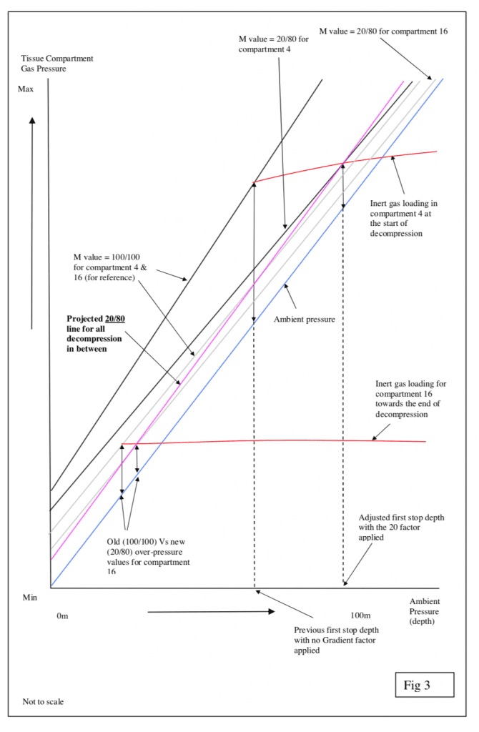
So a 20/80 gradient factor, which has been commonly used on deeper dives, would allow an over-pressure value of 20% (instead of 100%) of the difference between the ambient pressure and the allowed M value for the controlling compartment of the first or “deep stop” and 80% (instead of 100%) of the M value for the controlling compartments’ pressure difference at the shallow stop. The stops in between are calculated by drawing an over-pressure value line between the two points and plotting the new adjusted M values for each compartment in between. It assumes a linear calculation between the adjusted first and last M values.
In Figure 3 let’s assume that compartment 4 controls the deep stop and compartment 16 the shallow stop. Again, for clarity, the on-going compartment inert gas loading reductions are not shown past the M value point, neither are all the other compartment M values.
The major drawback of gradient factors is that the factors applied need to be adjusted for each depth/time exposure. For example, if you used the same 20/80 gradient factor for an 80 m dive, on a 30 m dive you might have an excess of decompression in shallow water because we know from experience that a gradient factor of close to 100/100 is reliable for this shallow water dive.
What does this mean? First, it is not necessarily appropriate to apply one gradient factor to a range of dive depths. What works deep may not work shallow. Secondly, it means just applying gradient factors in the first place may be too coarse a solution. Just drawing a straight line between the M value points and assuming the mid-water decompression follows this linear approach may not work. So how do we generate a refinement?
Stochastic modelling has been around in diving for some time. Decompression tables are generated based on statistical dive data of incidents; basically, points are plotted on a graph and an algorithm generated. So how could we use this to improve gradient factor modelling? Assuming the 100/100 factor is OK for a certain shallow dive and the 20/80 is OK for a particular deep dive, would it not be best to have a varying gradient factor depending on depth/time exposure and other factors? If we can be fairly certain of key decompression times for a range of depth/time exposures that are ‘safe’ and generate reasonable decompressions, we could use them to generate a gradient factor that varies accordingly. My term for this approach is a Variable Gradient Model (VGM).
VGM has the ability to use stochastic data and historically ‘proven’ decompression values in an algorithm and automatically adjust it for a range of depth/time exposure scenarios. The VGM software can be embedded into the dive computer, for example, in the MCM100, and its parameters can be adjusted using the screen below. Note that I also used VGM in my previous company’s [VR Technology Ltd.] VRx computers.
In summary, a VGM profile has the effect of padding the stops at certain decompression points while reducing stop times at others for a specific exposure scenario. What’s more, it changes them again automatically for different exposure scenarios and allows varying degrees of user input dependent on the application. VGM is a useful tool based on our current culminated experience. It brings together in one approach much of what we know and may help predict some of that which we do not.
Once data is available, many other variables could be built into a VGM matrix, such that with time and information it could continuously evolve to give increasingly accurate decompression predictions. While the modelling of the human body eludes us, VGM would appear to be a good solution to the current issues.
Dive Deeper:
InDepth: Gradient Factors in a Post-Deep Stops World by David Doolette.
TDI|SDI: REPROGRAMMING THE FUTURE: AN INTERVIEW WITH KEVIN GURR by Michael Menduno
Divernet: DELVING DEEPER INTO DEEP STOPS By Mark Powell
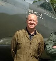
Kevin Gurr has been involved with Technical Diving since its inception in Europe. As well as being the first Technical Diving instructor outside the USA, he has led and been a part of many expeditions; the first sport dives on the Britannic in 1997, treasure hunting in the Pacific (and several other locations World-wide), filmmaking, and a dive on the Titanic in the MIR submarines to name a few.
As an engineer and diver he has developed several ground breaking products for the diving industry from trimix computers to rebreathers, including the Ace Profile, VR3, VRx computers, Pro Planner desktop decompression software, and the Ouroboros, Sentinel, Explorer and the MCM100 rebreathers. He lives in Dorset, England with wife Mandy, daughters Leyla and Amberlee, Neo the black Labrador, and various motorcycles.

